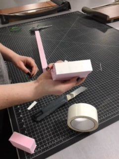
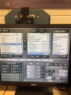
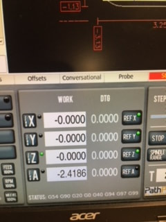
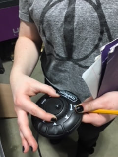
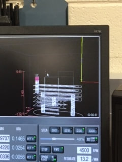
After changing the Fusion 360 settings to CAM, changing the units to inches, selected the origin and placed the z, x, and y coordinates in the right position, I had the Widget started in Fusion 360. Then I selected the stock side offset to 0 and the stock top offset to one, selected the 3d pocket clearing in order to select the flat end tool. I then edited this tool so the diameter was .25 in and the body length was 2 in. After doing so, I clicked the option under set up and changed the passes so that the maximum roughing stepdown was .25 in and changed both the radial and axial stock to 0. Then, after checking the simulation and making sure to 2d contour the bottom edge, I selected the post process to generate the g-code. Then, I cut 3 inches of foam for the widget and applied two sided sticky tape to the edge of the machine. After doing so, I used the tool shown in Figure 2 to move the tool along the x, y, and z coordinates so that the bit was on the edge of the design. Then, I zeroed the x, y, and z axis by selecting the left buttons shown in figure 1. Then I closed the machine doors and started the machine.
For this project, I learned more about Fusion 360 and how to use both 2d and 3d contouring. I also learned how to set up this machine and noticed how similar the mill is to the router. I learned more practical things as well; I accidentally left a bit of foam on the end of my cut (it wasn't quite 3 inches long) and the top of the bit started to move with the bit. So I learned to always double check my measurements (because I never want to hear the noise that machine made again). I also learned more about G-Code and how the two machines could use the same type of code to do similar tasks on different machines (though the details of the projects were very different).